

6 32 Socket Head Cap Screw Dimensions
6 32 Socket Head Cap Screw Dimensions
| Standard Socket Head Cap Screw Dimensions (Blend & Stainless Steel) ASME B18.3-2003 | |||||||||||||
|---|---|---|---|---|---|---|---|---|---|---|---|---|---|
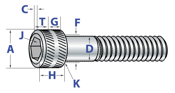
| Basic Spiral Diameter Click on the size to shop products | Trunk Bore (D) | Head Diameter (A) | Head Pinnacle (H) | Acme Chamfer or Radius (C) | Hex Socket Size (J) | Fillet Juncture Bore at Begetting Surface (F) | Cardinal Engage-ment (T) | Wall Thick-ness (Chiliad) | Bottom Chamfer or Radius (K) | ||||
| Max | Min | Max | Min | Max | Min | Max | Nom | Max | Min | Min | Min | Max | |
| 0 | 0.0600 | 0.0568 | 0.096 | 0.091 | 0.060 | 0.057 | 0.004 | 0.050 | 0.074 | 0.062 | 0.025 | 0.020 | 0.007 |
| 1 | 0.0730 | 0.0695 | 0.118 | 0.112 | 0.073 | 0.070 | 0.005 | 1/16 | 0.087 | 0.075 | 0.031 | 0.025 | 0.007 |
| 2 | 0.0860 | 0.0822 | 0.140 | 0.134 | 0.086 | 0.083 | 0.008 | 5/64 | 0.102 | 0.090 | 0.038 | 0.029 | 0.007 |
| 3 | 0.0990 | 0.0949 | 0.161 | 0.154 | 0.099 | 0.095 | 0.008 | five/64 | 0.115 | 0.102 | 0.044 | 0.034 | 0.007 |
| iv | 0.1120 | 0.1075 | 0.183 | 0.176 | 0.112 | 0.108 | 0.009 | 3/32 | 0.130 | 0.117 | 0.051 | 0.038 | 0.008 |
| five | 0.1250 | 0.1202 | 0.205 | 0.198 | 0.125 | 0.121 | 0.012 | iii/32 | 0.145 | 0.132 | 0.057 | 0.043 | 0.008 |
| vi | 0.1380 | 0.1329 | 0.226 | 0.218 | 0.138 | 0.134 | 0.013 | 7/64 | 0.158 | 0.144 | 0.064 | 0.047 | 0.008 |
| 8 | 0.1640 | 0.1585 | 0.270 | 0.262 | 0.164 | 0.159 | 0.014 | 9/64 | 0.188 | 0.172 | 0.077 | 0.056 | 0.008 |
| 10 | 0.1900 | 0.1840 | 0.312 | 0.303 | 0.190 | 0.185 | 0.018 | 5/32 | 0.218 | 0.202 | 0.090 | 0.065 | 0.008 |
| 1/four | 0.2500 | 0.2435 | 0.375 | 0.365 | 0.250 | 0.244 | 0.025 | iii/16 | 0.278 | 0.261 | 0.120 | 0.095 | 0.010 |
| v/16 | 0.3125 | 0.3053 | 0.469 | 0.457 | 0.312 | 0.306 | 0.033 | one/4 | 0.347 | 0.329 | 0.151 | 0.119 | 0.010 |
| 3/eight | 0.3750 | 0.3678 | 0.562 | 0.550 | 0.375 | 0.368 | 0.040 | 5/xvi | 0.415 | 0.397 | 0.182 | 0.143 | 0.010 |
| 7/16 | 0.4375 | 0.4294 | 0.656 | 0.642 | 0.438 | 0.430 | 0.047 | three/eight | 0.484 | 0.465 | 0.213 | 0.166 | 0.015 |
| ane/2 | 0.5000 | 0.4919 | 0.750 | 0.735 | 0.500 | 0.492 | 0.055 | three/8 | 0.552 | 0.531 | 0.245 | 0.190 | 0.015 |
| five/8 | 0.6250 | 0.6163 | 0.938 | 0.921 | 0.625 | 0.616 | 0.070 | i/2 | 0.689 | 0.664 | 0.307 | 0.238 | 0.015 |
| 3/four | 0.7500 | 0.7406 | 1.125 | 1.107 | 0.750 | 0.740 | 0.085 | 5/8 | 0.828 | 0.800 | 0.370 | 0.285 | 0.015 |
| 7/8 | 0.8750 | 0.8647 | 1.312 | 1.293 | 0.875 | 0.864 | 0.100 | 3/4 | 0.963 | 0.932 | 0.432 | 0.333 | 0.020 |
| 1 | 1.0000 | 0.9886 | i.500 | 1.479 | one.000 | 0.988 | 0.114 | 3/4 | 1.100 | one.068 | 0.495 | 0.380 | 0.020 |
| 1-1/four | 1.2500 | 1.2336 | 1.875 | 1.852 | 1.250 | one.236 | 0.144 | 7/eight | 1.370 | i.333 | 0.620 | 0.475 | 0.020 |
| 1-1/2 | 1.5000 | 1.4818 | two.250 | 2.224 | 1.500 | 1.485 | 0.176 | i | 1.640 | i.601 | 0.745 | 0.570 | 0.020 |
| Socket Cap Screws : Nominal Thread Length | |||||||
|---|---|---|---|---|---|---|---|
| Tolerance on Length | Nominal Spiral Size | Nominal Spiral Length | |||||
| Up to i" | Over i" - two-ane/2" | Over two-ane/2" - 6" | Over 4" - 6" | ||||
| 0 thru 3/8 | -.03 | -.04 | -.06 | -.12 | |||
| vii/xvi thru 3/four | -.03 | -.06 | -.08 | -.12 | |||
| vii/8 thru 1-1/2 | -.05 | -.10 | -.14 | -.20 | |||
| Mechanical Properties of Socket Cap Screws - Alloy and Stainless Steel | ||||||||||||||
|---|---|---|---|---|---|---|---|---|---|---|---|---|---|---|
| Nominal Size | Tensile Strength (lbs., min) | Yield Strength (lbs., min) | Body Department | Tightening Torque (in. - lbs.) | ||||||||||
| UNRC | UNRF | UNRC | UNRF | Unmarried Shear Forcefulness (lbs., min.) | UNRC | UNRF | ||||||||
| Alloy | Stainless | Blend | Stainless | Alloy | Stainless | Alloy | Stainless | Alloy | Stainless | Alloy | Stainless | Alloy | Stainless | |
| 0 | - | - | 320 | 145 | - | - | 290 | 72 | 305 | 130 | - | - | 2.half-dozen | 1.4 |
| 1 | 475 | - | 500 | 220 | 425 | - | 450 | 111 | 450 | 190 | 4.5 | - | 4.8 | 2.iii |
| 2 | 665 | 295 | 710 | - | 600 | 185 | 635 | - | 625 | 260 | seven.5 | 3.8 | 8.0 | - |
| three | 875 | - | 940 | - | 790 | - | 845 | - | 830 | - | 11.0 | - | 12.0 | - |
| four | 1,090 | 480 | 1,190 | - | 975 | 240 | 1,070 | - | 1,060 | 350 | 16.0 | 6.0 | 18.0 | - |
| 5 | 1,430 | - | ane,490 | - | i,290 | - | 1,345 | - | ane,325 | - | 24.0 | - | 24.0 | - |
| 6 | 1,640 | 725 | ane,825 | - | ane,470 | 363 | i,645 | - | 1,615 | 375 | 30.0 | xv.0 | 34.0 | - |
| 8 | 2,520 | one,120 | 2,650 | - | 2,270 | 560 | two,385 | - | ii,280 | 670 | 55.0 | 28.0 | 58.0 | - |
| 10 | 3,150 | 1,400 | 3,600 | ane,600 | two,835 | 701 | 3,240 | 800 | 3,060 | 950 | 79.0 | twoscore.0 | 90.0 | 46.0 |
| 1/4 | five,725 | 2,550 | 6,550 | 2,910 | 5,150 | 1,273 | v,900 | 1,455 | v,295 | two,200 | 200.0 | 95.0 | 230.0 | 109.0 |
| 5/xvi | 9,430 | 4,200 | x,440 | 4,645 | viii,490 | ii,100 | 9,395 | 2,230 | 8,285 | 3,450 | 415.0 | 170.0 | 460.0 | 188.0 |
| 3/8 | 13,950 | six,100 | xv,805 | vii,025 | 12,555 | 3,100 | 14,225 | three,510 | 11,910 | 4,970 | 740.0 | 301.0 | 845.0 | 341.0 |
| seven/xvi | 19,135 | - | 21,365 | - | 17,220 | - | 19,230 | - | 16,200 | - | 1,190.0 | - | 1,305.0 | - |
| one/2 | 25,540 | 11,350 | 28,780 | - | 22,990 | 5,675 | 25,905 | - | 21,175 | viii,840 | i,800.0 | 750.0 | 2,065.0 | - |
| v/8 | 38,400 | - | 43,500 | - | 34,550 | - | 39,150 | - | 31,300 | - | three,400.0 | - | three,800.0 | - |
| three/4 | 56,750 | - | 63,400 | - | 51,100 | - | 57,050 | - | 45,050 | - | half dozen,000.0 | - | 6,750.0 | - |
| 7/8 | 78,500 | - | 86,500 | - | 70,700 | - | 77,850 | - | 61,350 | - | 8,250.0 | - | nine,200.0 | - |
| 1 | 103,000 | - | 112,700 | - | 92,700 | - | 101,450 | - | 80,100 | - | 12,500.0 | - | 13,000.0 | - |
| 1-1/4 | 164,700 | - | 182,400 | - | 148,250 | - | 164,150 | - | 125,100 | - | 25,000.0 | - | 27,750.0 | - |
| ane-1/2 | 238,800 | - | 268,800 | - | 215,950 | - | 241,900 | - | 180,200 | - | 43,500.0 | - | 49,000.0 | - |
| Trunk and Grip Lengths of Standard Head Socket Cap Screws ASME B18.three-2003 | ||||||||||||||||||||||||||||||||||||
|---|---|---|---|---|---|---|---|---|---|---|---|---|---|---|---|---|---|---|---|---|---|---|---|---|---|---|---|---|---|---|---|---|---|---|---|---|
| Nominal Size (D) | 0 | 1 | two | 3 | 4 | five | six | eight | 10 | ane/4 | 5/sixteen | iii/viii | 7/16 | i/2 | 5/8 | 3/iv | seven/8 | 1 | ||||||||||||||||||
| Basic Thread Length (LT) | 0.500 | 0.625 | 0.625 | 0.625 | .750 | .750 | .750 | .875 | .875 | one.000 | ane.125 | i.250 | 1.375 | ane.500 | one.750 | 2.000 | two.250 | 2.500 | ||||||||||||||||||
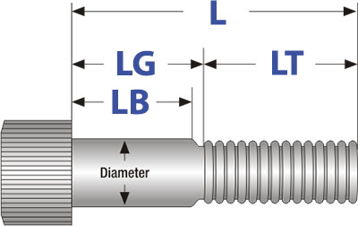
| Nominal Length (L) | LG | LB | LG | LB | LG | LB | LG | LB | LG | LB | LG | LB | LG | LB | LG | LB | LG | LB | LG | LB | LG | LB | LG | LB | LG | LB | LG | LB | LG | LB | LG | LB | LG | LB | LG | LB |
| i.00 | 0.fifty | 0.44 | 0.25 | 0.17 | 0.25 | 0.xvi | 0.25 | 0.fifteen | 0.25 | 0.12 | 0.25 | 0.12 | ||||||||||||||||||||||||
| 1.25 | 0.75 | 0.69 | 0.62 | 0.55 | 0.62 | 0.54 | 0.62 | 0.52 | 0.25 | 0.12 | 0.25 | 0.12 | 0.50 | 0.34 | 0.38 | 0.22 | 0.38 | 0.17 | ||||||||||||||||||
| 1.50 | 0.88 | 0.80 | 0.88 | 0.79 | 0.88 | 0.77 | 0.75 | 0.62 | 0.75 | 0.62 | 0.50 | 0.34 | 0.38 | 0.22 | 0.38 | 0.17 | 0.fifty | 0.25 | ||||||||||||||||||
| 1.75 | 1.12 | 1.04 | 1.12 | one.02 | 0.75 | 0.62 | 0.75 | 0.62 | 1.00 | 0.84 | 0.88 | 0.72 | 0.88 | 0.67 | 0.50 | 0.25 | 0.62 | 0.35 | 0.50 | 0.19 | ||||||||||||||||
| 2.00 | 1.38 | i.27 | ane.25 | one.12 | 1.25 | 1.12 | ane.00 | 0.84 | 0.viii | 0.72 | 0.88 | 0.67 | 1.00 | 0.75 | 0.62 | 0.35 | 0.50 | 0.19 | 0.62 | 0.27 | ||||||||||||||||
| two.25 | i.25 | 1.12 | 1.25 | ane.12 | i.50 | ane.34 | 1.38 | ane.22 | i.38 | ane.17 | one.00 | 0.75 | 1.12 | 0.85 | one.00 | 0.69 | 0.62 | 0.27 | 0.75 | 0.36 | ||||||||||||||||
| two.50 | 1.75 | ane.62 | one.50 | i.34 | 1.38 | 1.22 | i.38 | 1.17 | 1.50 | one.25 | 1.12 | 0.85 | 1.00 | 0.69 | i.12 | 0.77 | 0.75 | 0.36 | 0.75 | 0.30 | ||||||||||||||||
| 2.75 | two.00 | 1.84 | 1.88 | 1.72 | 1.88 | one.67 | 1.fifty | i.25 | i.62 | 1.35 | 1.50 | 1.19 | 1.12 | 0.77 | 0.75 | 0.36 | 0.75 | 0.thirty | ||||||||||||||||||
| iii.00 | i.88 | 1.72 | ane.88 | 1.67 | 2.00 | one.75 | 1.62 | 1.35 | one.l | 1.xix | 1.62 | ane.27 | one.50 | 1.12 | 0.75 | 0.30 | 1.00 | 0.50 | ||||||||||||||||||
| 3.25 | 2.38 | 2.17 | two.00 | i.75 | 2.12 | 1.85 | 2.00 | i.69 | one.62 | 1.27 | i.50 | 1.12 | one.50 | 4.04 | 1.00 | 0.50 | ane.00 | 0.44 | ||||||||||||||||||
| three.fifty | ii.l | two.25 | two.12 | 1.85 | ii.00 | i.69 | 2.12 | i.77 | 1.50 | one.12 | 1.50 | one.04 | 1.00 | 0.50 | 1.00 | 0.44 | 1.00 | 0..38 | ||||||||||||||||||
| 4.00 | 3.00 | 2.75 | 2.62 | ii.35 | 2.l | 2.nineteen | 2.62 | two.27 | 2.25 | 1.86 | 2.25 | one.lxxx | 2.00 | 1.l | ane.00 | 0.44 | 1.00 | 0.38 | ||||||||||||||||||
| 4.50 | three.fifty | 3.25 | three.12 | 2.85 | 3.00 | 2.69 | 3.12 | ii.77 | iii.00 | 2.62 | 2.25 | 1.80 | 2.00 | one.50 | two.00 | 1.44 | two.00 | one.38 | ||||||||||||||||||
| 5.00 | 4.00 | three.75 | 3.62 | iii.35 | iii.50 | 3.19 | 3.62 | 3.27 | 3.00 | 2.62 | 3.00 | two.54 | three.00 | 2.50 | ii.00 | 1.44 | 2.00 | 1.38 | ||||||||||||||||||
| 5.fifty | four.12 | 3.85 | 4.00 | 3.69 | 4.12 | 3.77 | three.75 | three.36 | three.75 | 3.30 | iii.00 | 2.l | 3.00 | 2.44 | 3.00 | 2.38 | ||||||||||||||||||||
| 6.00 | 4.62 | 4.35 | 4.50 | four.nineteen | four.62 | 4.27 | iv.fifty | 4.12 | three.75 | three.thirty | 4.00 | 3.50 | iii.00 | 2.44 | 3.00 | 2.38 | ||||||||||||||||||||
| 6.50 | 5.00 | 4.69 | five.12 | four.77 | 4.fifty | 4.12 | 4.l | 4.04 | 4.00 | iii.50 | 4.00 | three.44 | iv.00 | 3.38 | ||||||||||||||||||||||
| 7.00 | v.50 | v.19 | 5.62 | 5.27 | 5.25 | iv.86 | 5.25 | 4.80 | v.00 | 4.50 | 4.00 | iii.44 | 4.00 | iii.38 | ||||||||||||||||||||||
| viii.00 | half-dozen.62 | vi.27 | 6.00 | v.62 | 6.00 | 5.54 | half dozen.00 | five.fifty | 5.00 | four.44 | v.00 | 4.38 | ||||||||||||||||||||||||
| 9.00 | seven.62 | 7.27 | 7.00 | 6.62 | 6.75 | 6.30 | vii.00 | half dozen.fifty | 6.00 | v.44 | 6.00 | 5.38 | ||||||||||||||||||||||||
| 10.00 | 8.00 | vii.62 | 7.75 | 7.30 | viii.00 | seven.l | seven.00 | 6.44 | 7.00 | 6.38 | ||||||||||||||||||||||||||
| 11.00 | ix.25 | 8.80 | 9.00 | 8.50 | 8.00 | 7.44 | 8.00 | 7.38 | ||||||||||||||||||||||||||||
| 12.00 | x.25 | 9.80 | 10.00 | ix.50 | 9.00 | 8.44 | 9.00 | 8.38 | ||||||||||||||||||||||||||||
Notes:
- The basic thread lengths (LT) listed directly below the nominal sizes in the tabular array above represents the nominal length up to which all screws of that diameter shall be fully threaded.
- To decide the threaded portion of the screws with a nominal length greater than LT, subtract the minimum design grip length (LG) from the nominal length (L).
| Socket Cap Screws : Functioning & Mechanical Stats | ||||||
|---|---|---|---|---|---|---|
| Standard Caput - Alloy Steel
| Standard Head - Stainless Steel
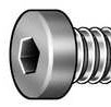
| Low Head - Alloy Steel
| Push Caput - Alloy Steel | Flat Head - Alloy Steel | ||
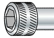
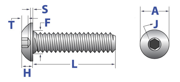
| Descriptions | An externally threaded fastener with unified threads, a cylindrical head (with a flat, chamfered summit surface), knurled cylindrical sides and hexagonal recess. | An externally threaded fastener with unified threads, a cylindrical head (with a flat, chamfered acme surface), knurled cylindrical sides and hexagonal recess. | Head superlative is l% of a standard socket caput and the socket size is smaller. | Similar thread design as a socket cap screw, but the dome-shaped head is wider and has a lower contour. | Similar to a push caput socket spiral, but with an 82-caste countersunk flat head. | |
| Applications/Advantages | Precision assembly piece of work and applications requiring a well-tooled appearance. Greater tensile strength than same size Grade five or 8 hex head cap screws while requiring less surface area due to the internal wrenching. | Stainless socket screws have less tensile and yield strength than blend sockets, but superior corrosion resistance. They also retain mechanical and performance capabilities at higher than ambient temperatures. | Useful in situations where clearance is express. *Due to design constraints, low head cap screws cannot withstand same preloads every bit standard socket cap screws. | Used when a wider bearing surface or smoother, finished appearance is desired. Designed for light fastening applications. Not recommended for critical, high-force applications. | Used when a flush mount, high-strength screw is required. Often used for tools and dies where moving parts laissez passer over an area. | |
| Textile | Alloy steel with min 31% Carbon, max 0.040% Phosphorus, max 0.045% Sulfur and one or more than of the following elements in sufficient quantity to run into strength requirements listed below: chromium, nickel, molybdenum or vanadium. | 302, 303, 304, 305, 384, XM1, or XM7 blend | Alloy steel with min 31% Carbon, max 0.040% Phosphorus, max 0.045% Sulfur and ane or more of the following elements in sufficient quantity to run into strength requirements listed below: chromium, nickel, molybdenum or vanadium. | Alloy steel with min 0.28 to 0.50% Carbon, max 0.040% Phosphorus, max 0.035% Sulfur and i or more of the following elements in sufficient quantity to come across strength requirements listed below: chromium, nickel, molybdenum or vanadium. | Alloy steel with min 0.28 to 0.50% Carbon, max 0.040% Phosphorus, max 0.045% Sulfur and one or more than of the following elements in sufficient quantity to meet forcefulness requirements listed below: chromium, nickel, molybdenum or vanadium. | |
| Heat Handling | Oil quenching from above the transformation temperature, tempered at a temp. not lower than 650 degrees F. | The only rut treatment usually bachelor on austenitic stainless alloys is annealing, done at approx. 1900-degrees F to a dead soft condition and is not normally thermally reversible. | Oil quenching from above the transformation temperature, tempered at a temp. not lower than 650 degrees F. | Oil quenching from to a higher place the transformation temperature, tempered at a temp. non lower than 650 degrees F. | Oil quenching from to a higher place the transformation temperature, tempered at a temp. not lower than 650 degrees F. | |
| Hardness | 0 - 1/two" D: Rockwell C39 min. 5/viii" D & larger: Rockwell C37 min. | Rockwell B80 min. | Rockwell C38 min. | Rockwell C38 - 44 | 0 - 1/2" D: Rockwell C39 - 44 Over 1/2" D: Rockwell C37 - 44 | |
| Tensile Strength | 0 - 1/2" D: 180,000 psi min. 5/8" D & larger: 170,000 psi min. | 80,000 psi min. | 170,000 psi min. | 180,000 psi min. (material just) | 0 - one/2" D: 145,000 psi min. Over 1/2" D: 135,000 psi min. | |
| Yield Strength | 0 - one/two" D: 162,000 psi min. 5/viii" D & larger: 153,000 psi min. | 30,000 psi min. | 150,000 psi min. | 160,000 psi min. (textile but) | 153,000 psi min. (over i/2" diam.) | |
| Elongation | 10% min (Applies to machined specimens at least 4D in length where D equals the nominal diameter of the screw.) | 10% min (Applies to machined specimens at least 4D in length where D equals the nominal diameter of the spiral.) | 10% min (Applies to machined specimens at least 4D in length where D equals the nominal bore of the screw.) | 8% min (Applies to machined specimens at least 4D in length where D equals the nominal diameter of the screw.) | 8% min (Applies to machined specimens over 1/2" diam., at least 4D in length where D equals the nominal diameter of the screw.) | |
| Reduction of Expanse | 33% min (machined specimens) | 30% min (machined specimens) | 33% min (machined specimens) | 35% min (machined specimens) | 35% min (machined specimen's over 1/2" diam.) | |


Button Caput Socket Cap Screws: Dimensions & Mechanical Properties
| Push Caput Socket Cap Screw Dimensions & Mechanical Backdrop (Blend Steel) ASME B18.3-2003 | ||||||||||||||
|---|---|---|---|---|---|---|---|---|---|---|---|---|---|---|
| Nominal size | Caput Diameter (A) | Head Height (H) | Head Side Tiptop (Southward) | Hex Socket Size (J) | Key Engage- ment (T) | Fillet Transition Diameter (F) | Max Standard Length (L) | Tensile Test Load | Single Shear Strength of Trunk | Seating Torques (in./lbs.) | ||||
| Max | Min | Max | Min | Ref | Nom | Min | Max | Min | Nom | lb. | lbs., min. | Coarse Thread | Fine Thread | |
| 4 | 0.213 | 0.201 | 0.059 | 0.051 | 0.015 | ane/16 | 0.035 | 0.132 | 0.50 | 0.50 | 840 | 950 | 7.0 | 8 |
| vi | 0.262 | 0.250 | 0.073 | 0.063 | 0.015 | 5/64 | 0.044 | 0.158 | 0.63 | 0.63 | 1,260 | i,400 | xiii | 15 |
| eight | 0.312 | 0.298 | 0.087 | 0.077 | 0.015 | 3/32 | 0.052 | 0.194 | 0.75 | 0.75 | ane,940 | 2,000 | 25 | 26 |
| 10 | 0.361 | 0.347 | 0.101 | 0.091 | 0.020 | 1/8 | 0.070 | 0.220 | one.00 | 1.00 | ii,440 | ii,700 | 45 | 48 |
| 1/4 | 0.437 | 0.419 | 0.132 | 0.122 | 0.031 | 5/32 | 0.087 | 0.290 | 1.00 | 1.00 | 4,430 | 4,700 | 95 | 110 |
| 5/16 | 0.547 | 0.527 | 0.166 | 0.152 | 0.031 | 3/xvi | 0.105 | 0.353 | 1.00 | 1.00 | 7,300 | seven,300 | 190 | 210 |
| 3/8 | 0.656 | 0.636 | 0.199 | 0.185 | 0.031 | vii/32 | 0.122 | 0.415 | ane.25 | 1.25 | 10,800 | 10,600 | 300 | 300 |
| i/2 | 0.875 | 0.851 | 0.265 | 0.245 | 0.046 | v/16 | 0.175 | 0.560 | 2.00 | 2.00 | 19,800 | 18,800 | 900 | 960 |
| 5/eight | 1.000 | 0.970 | 0.331 | 0.311 | 0.062 | 3/8 | 0.210 | 0.685 | two.00 | two.00 | 31,500 | 29,400 | 1,700 | 1,900 |
| Push button Head Socket Cap Screws : Nominal Thread Length | |||||
|---|---|---|---|---|---|
| Tolerance on Length | Nominal Screw Size | Nominal Spiral Length | |||
| Upwards to 1" (Inclusive) | Over ane" - 2-1/ii" (Inclusive) | ||||
| 0 thru 3/eight (Inclusive) | -.03 | -.04 | |||
| 1/2 and five/eight (Inclusive) | -.03 | -.06 | |||
Depression Caput Socket Cap Screws: Dimensions & Mechanical Properties
| Low Head Socket Cap Screw Dimensions & Mechanical Properties (Alloy Steel) ASME B18.iii-2003 | ||||||||||||
|---|---|---|---|---|---|---|---|---|---|---|---|---|
| Nominal size | Basic Screw Bore (D) | Torso Diameter (F) | Head Bore (A) | Head Acme (H) | Hex Socket Size (J) | Key Engage- ment (T) | Tensile Strength (lbs./min) | Tightening Torque (in./lbs.) | ||||
| Max | Min | Max | Min | Max | Min | Min | UNRC | UNRF | ||||
| 8 | 0.1640 | 0.1640 | 0.1585 | 0.270 | 0.265 | 0.085 | 0.079 | 0.078 | 0.060 | 2,310 | 2,440 | 19.4 |
| 10 | 0.1900 | 0.1900 | 0.1840 | 0.312 | 0.307 | 0.098 | 0.092 | 0.094 | 0.072 | ii,890 | 3,300 | 33.five |
| 1/4 | 0.2500 | 0.2500 | 0.2435 | 0.375 | 0.369 | 0.127 | 0.121 | 0.125 | 0.094 | 5,250 | 6,000 | 77.nine |
| v/16 | 0.3125 | 0.3125 | 0.3053 | 0.437 | 0.431 | 0.158 | 0.152 | 0.156 | 0.110 | 8,650 | 9,550 | 156.0 |
| 3/8 | 0.3750 | 0.3750 | 0.3678 | 0.562 | 0.556 | 0.192 | 0.182 | 0.188 | 0.115 | 12,800 | xiv,450 | 273.0 |
| 1/ii | 0.5000 | 0.5000 | 0.4919 | 0.750 | 0.743 | 0.254 | 0.244 | 0.250 | 0.151 | 23,400 | 26,350 | 615.0 |
| Depression Head Socket Cap Screws : Nominal Thread Length | |||||
|---|---|---|---|---|---|
| Tolerance on Length | Nominal Screw Size | Nominal Screw Length | |||
| Upward to 1" (Inclusive) | Over 1" - two-1/2" (Inclusive) | ||||
| 0 thru 3/8 | -.03 | -.04 | |||
| one/ii | -.03 | -.06 | |||
Flat Caput Socket Cap Screws: Dimensions & Mechanical Properties

| Flat Head Socket Cap Screw Dimensions (Blend Steel) ASME B18.3-2003, Blue Devil | |||||||||||||||||
|---|---|---|---|---|---|---|---|---|---|---|---|---|---|---|---|---|---|
| Nominal Size | Body Diameter (D) | Head Diameter (A) | Caput Height (H) | Protrusion Cuff Bore (G) | Protrusion (P) | Hex Socket Size (J) | Key Appoint-ment (T) | Fillet Transi-tion Diam. (F) | Tensile Strength (lbs Min) | Single Shear Strength of Body | Recommended Seating Torques (in/lbs) | ||||||
| Max | Min | Theoretical Sharp Max | Abs. Min | Ref | Max | Min | Max | Min | Nom | Min | Max | UNRC | UNRF | lbs., Min | Fibroid Thread | Fine Thread | |
| four | 0.1120 | 0.1075 | 0.255 | 0.218 | 0.083 | 0.172 | 0.174 | 0.049 | 0.036 | 1/xvi | 0.055 | 0.136 | 900 | - | 940 | 8. | - |
| 5 | 0.1250 | 0.1202 | 0.281 | 0.240 | 0.090 | 0.196 | 0.195 | 0.051 | 0.037 | 5/64 | 0.061 | 0.153 | 1,185 | - | 1,180 | 12. | - |
| 6 | 0.1380 | 0.1329 | 0.307 | 0.263 | 0.097 | 0.220 | 0.219 | 0.052 | 0.037 | 5/64 | 0.066 | 0.168 | 1,350 | - | 1,440 | 15. | - |
| 8 | 0.1640 | 0.1585 | 0.359 | 0.311 | 0.112 | 0.267 | 0.266 | 0.055 | 0.039 | 3/32 | 0.076 | 0.194 | 2,085 | - | ii,030 | thirty. | - |
| 10 | 0.1900 | 0.1840 | 0.411 | 0.359 | 0.127 | 0.313 | 0.312 | 0.058 | 0.041 | 1/8 | 0.087 | 0.220 | 2,610 | two,610 | 2,720 | twoscore. | 45. |
| 1/4 | 0.2500 | 0.2435 | 0.531 | 0.480 | 0.161 | 0.424 | 0.423 | 0.064 | 0.043 | 5/32 | 0.111 | 0.280 | iv,750 | 4,750 | 4,710 | 100. | 110. |
| 5/xvi | 0.3125 | 0.3053 | 0.656 | 0.600 | 0.198 | 0.539 | 0.538 | 0.070 | 0.047 | 3/16 | 0.135 | 0.343 | seven,800 | seven,800 | vii,360 | 200. | 220. |
| iii/8 | 0.3750 | 0.3678 | 0.781 | 0.720 | 0.234 | 0.653 | 0.652 | 0.076 | 0.050 | 7/32 | 0.159 | 0.405 | 11,600 | eleven,600 | 10,600 | 350. | 400. |
| 7/sixteen | 0.4375 | 0.4294 | 0.844 | 0.781 | 0.234 | 0.690 | 0.689 | 0.092 | 0.063 | 1/4 | 0.159 | 0.468 | xv,900 | xv,900 | 14,400 | 560. | - |
| 1/2 | 0.5000 | 0.4919 | 0.938 | 0.872 | 0.251 | 0.739 | 0.738 | 0.119 | 0.087 | five/16 | 0.172 | 0.530 | 21,200 | 21,200 | 18,850 | 850. | 1,000. |
| 5/8 | 0.6250 | 0.616 | 1.188 | 1.112 | 0.324 | 0.962 | 0.961 | 0.135 | 0.096 | 3/viii | 0.220 | 0.655 | 33,800 | 33,800 | 29,450 | 1,700 | - |
| 3/iv | 0.7500 | 0.7406 | 1.438 | one.355 | 0.396 | 1.186 | 1.185 | 0.150 | 0.105 | 1/2 | 0.220 | 0.780 | fifty,000 | 50,000 | 42,400 | 3,000 | - |
| Flat Head Socket Cap Screws : Nominal Thread Length | ||||||
|---|---|---|---|---|---|---|
| Tolerance on Length | Nominal Spiral Size | Nominal Screw Length | ||||
| Upwards to i" | Over 1" - 2-1/ii" | Over 2-one/ii" - 6" | ||||
| 0 thru three/viii (Inclusive) | -.03 | -.04 | -.06 | |||
| 7/sixteen thru 3/4 (Inclusive) | -.03 | -.06 | -.08 | |||
| Torso and Grip Lengths of Apartment Head Socket Cap Screws ASME B18.3-2003 | ||||||||||||||||||||||||
|---|---|---|---|---|---|---|---|---|---|---|---|---|---|---|---|---|---|---|---|---|---|---|---|---|
| Nominal Size | 4 | 5 | 6 | 8 | 10 | i/4 | 5/16 | 3/8 | 7/16 | one/two | five/eight | 3/4 | ||||||||||||
| LT Min. | .750 | .750 | .750 | .875 | .875 | 1.000 | i.125 | one.250 | 1.375 | 1.500 | 1.750 | 2.000 | ||||||||||||
| LTT Max | 0.99 | one.00 | 1.05 | 1.19 | 1.27 | 1.50 | 1.71 | 1.94 | 2.17 | 2.38 | ii.82 | 3.25 | ||||||||||||
| Nominal Length | LGH | LBH | LGH | LBH | LGH | LBH | LGH | LBH | LGH | LBH | LGH | LBH | LGH | LBH | LGH | LBH | LGH | LBH | LGH | LBH | LGH | LBH | LGH | LBH |
| 1.25 | 0.fifty | 0.38 | 0.50 | 0.38 | 0.fifty | 0.34 | 0.38 | 0.22 | ||||||||||||||||
| 1.50 | 0.50 | 0.38 | 0.fifty | 0.38 | 0.50 | 0.34 | 0.38 | 0.22 | 0.62 | 0.42 | ||||||||||||||
| 1.75 | 1.00 | 0.38 | one.00 | 0.88 | i.00 | 0.84 | 0.8 | 0.72 | 0.62 | 0.42 | 0.75 | 0.50 | ||||||||||||
| 2.00 | one.00 | 0.38 | 1.00 | 0.88 | one.00 | 0.84 | 0.88 | 0.72 | 1.12 | 0.92 | 0.75 | 0.50 | 0.88 | 0.threescore | ||||||||||
| 2.25 | ane.fifty | 1.34 | i.38 | 1.22 | 1.62 | i.42 | 1.25 | 1.00 | 0.88 | 0.threescore | 1.00 | 0.69 | ||||||||||||
| 2.fifty | 1.38 | 1.72 | 2.12 | one.92 | 1.75 | 1.fifty | 1.38 | 1.10 | 1.00 | 0.69 | 1.12 | 0.77 | 1.00 | 0.62 | ||||||||||
| 3.00 | two.62 | ii.42 | 2.25 | two.00 | 1.88 | ane.threescore | 1.fifty | 1.nineteen | i.62 | one.27 | i.00 | 0.62 | ||||||||||||
| 3.50 | 2.38 | 2.ten | 2.00 | i.69 | two.12 | 1.77 | one.75 | 1.36 | i.50 | ane.04 | one.l | 1.00 | ||||||||||||
| 4.00 | 2.88 | ii.60 | 2.l | 2.19 | ii.62 | 2.27 | 2.50 | 2.12 | two.25 | 1.80 | 1.50 | 1.00 | ||||||||||||
| 4.50 | iii.38 | 3.10 | 3.00 | ii.69 | 3.12 | 2.77 | two.50 | ii.12 | 2.25 | ane.80 | 2.50 | 2.00 | ||||||||||||
| 5.00 | 3.88 | 3.threescore | iii.50 | iii.19 | 3.62 | 3.27 | 3.25 | 2.86 | iii.00 | ii.54 | 2.50 | ii.00 | ||||||||||||
| 5.50 | 4.38 | 4.x | iv.00 | 3.69 | 4.12 | 3.77 | 4.00 | three.62 | 3.75 | 3.30 | 3.l | 3.00 | ||||||||||||
| six.00 | 4.88 | 4.lx | 4.50 | 4.xix | 4.62 | 4.27 | 4.00 | 3.62 | 3.75 | three.thirty | iii.50 | iii.00 | ||||||||||||
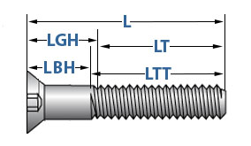
* Annotation: For screws of nominal lengths longer than those for which LGH and LBH values tabulated in this table and for screws over one inch in bore, the maximum grip gaging length LGH and the minimum body length LBH of the screws shall exist determined as follows: LGH = L - LT and LGH = L - LTT where 50 = nominal length, LT = minimum thread length, and LTT = maximum total thread length.
6 32 Socket Head Cap Screw Dimensions
Posted by: maloneyandla1965.blogspot.com
0 Response to "6 32 Socket Head Cap Screw Dimensions"
Post a Comment